
With the Window to Viewport Transformation, our goal is to transform the real-world coordinates (i.e. pair of x and y that indicate respectively the coordinate on the x-axis and on the y one) to the viewport ones (the screen coordinates).
As a first step, we have to identify the real-world window which we want to project in our viewport because we may be interested in specific portions of our real-world chart and this is useful to maintain its original shape. How can we do this? We can easily obtain this with a linear transform: in practice, it’s like we consider the real-world window and we stretch or shrink it to fit inside the viewport.
The coordinates of the viewport on the screen are completely different from the real-world window: in the first case, we are measuring pixels, in the second one we are measuring two variables that could have different units of measure. So we need to know how to transform each point in the real world (x_w, y_w) to a viewport point (x_d, y_d); first of all, remind that the origin of device points isn’t in the bottom-left corner, but in the top -left, therefore the y axis on the device is flipped respect to the cartesian system
What we want to find are 2 functions that given the real-world point give us its x and y to represent that point in the viewport:
![\[ \begin{cases} x= f_x(x_w)\\ y=f_y(y_w) \\ \end{cases} \]](https://emanueleseminara.it/wp-content/ql-cache/quicklatex.com-2d81facabf1bd6790d766ddd9de4f409_l3.png "Rendered by QuickLaTeX.com")
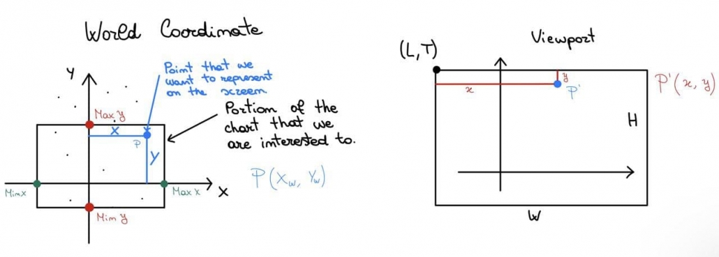
To find those functions that can solve our problem, we need to keep track of the viewport size and also of the coordinates of its top-left corner that we indicate with (L, T); for what regards the real world, we will need: MinX, MinY, MaxX and MaxY.

What is written below refers to this image above.
The green segment should correspond to the blue one: for instance, if the green segment is 1/3 of the Rx, we want also that the blue one will be 1/3 of W in order to maintain the proportion. So, (x – MinX)/Rx is the proportion factor which, if multiplied by W, will give us the blue segment; however, to obtain viewport x, we have to add to our blue segment L.
To conclude, viewport x will be given by the following:
![\[ x=L+\frac{x-x_{min}}{R_x}\cdot w \]](https://emanueleseminara.it/wp-content/ql-cache/quicklatex.com-7244a381fedf08d95591af1b229f78a3_l3.png "Rendered by QuickLaTeX.com")
The same can be done for Y, paying attention to the fact that the y-axis is flipped in the viewport with respect to the cartesian system.
The proportion of the red segment is: (y – MinY)/Ry, which multiplied by H, gives us the yellow segment.
What we are searching for, though, isn’t the yellow segment, but the orange one.
So, how could we obtain the orange segment? It’s just H – yellowSegment, i.e. H – H * (y – MinY)/Ry, and adding T we obtain the viewport y.
Here’s the formula to obtain the viewport y:
![\[ y=T+H-\frac{y-y_{min}}{R_y}\cdot h \]](https://emanueleseminara.it/wp-content/ql-cache/quicklatex.com-7460564b211a3124bdcf7845e716bb60_l3.png "Rendered by QuickLaTeX.com")
Useful coding for the conversion from a real point to the viewport one:
private int X_Viewport(double realX, double minX_Window, double rangeX, Rectangle viewport)
{
   //converting
   return (int)(viewport.Left + viewport.Width * (realX – minX_Window) / rangeX);
}

private int Y_Viewport(double realY, double minY_Window, double rangeY, Rectangle viewport)
{
   //converting
   return (int)(viewport.Top + viewport.Height – viewport.Height * (realY – minY_Window) / rangeY);
}
Leave a Reply
Want to join the discussion?Feel free to contribute!